Prop: Oblivion Gate Lamp
Let the Gates of Oblivion be open!
The Tale Begins...
Who wouldn't want to open up a gate to Oblivion on their nightstand, just me?
I've always pondered about making an Oblivion gate, whether it be some giant Minecraft build, or a small house prop. Of course one could always sculpt one in clay and glaze it various colours, but for such fine details, clay tends to look soft and bulbous. I knew I wanted to make one, but didn't know where to start.
After a few years of on and off again coming back to this idea, I figured I would tackle a new proficiency with this. Previously, any 3D model I've made had usually been an edit of an existing 3D model/mesh, or a basic model made in some CAD software, such as 123Design. But I wanted to make my own models now, and to do it, I wanted to learn Blender.
So the plan was setout to at least get myself a model of an Oblivion gate, so I could maybe 3D print it and from there figure out what to do. Once it was sculpted and made 3D printable, then I would have to figure out how to make it unique.
The Amulet of Kings is... a pie?
A Raspberry Pi, to be exact
Right around the time I was looking for a way to make my planned Oblivion gate unique, the Raspberry Pi Foundation announced their newest product, the Raspberry Pi Pico.
This wasn't the same as their SBC (Single-Board Computers). This was directly a microcontroller, competition to others such as the well known Arduinos, Teensys, AT chips and more. Here's the kicker - they were $5, had a pretty powerful chip and plenty of pins. For someone who struggled to find cheap microcontrollers such as Arduino's and ESP modules, this was too good to pass up.
It didn't take long to convince myself to order a few. Mere minutes after I placed the order I realized - I can use this to power and animate LEDs for the Oblivion gate.
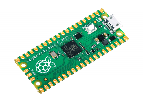
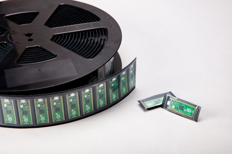
Raspberry Pi Pico (Left) & a reel of Picos (Right). Credit: Raspberry Pi Foundation.
Opening the Gates isn't easy
No wonder it takes a plot to assassinate the Emperor
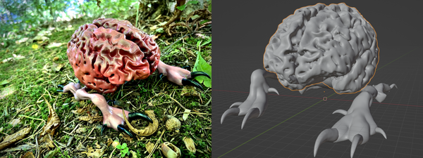
I began the work with what was probably the most time consuming part of the process, as I am an amateur sculptor and 3D modeler at best.
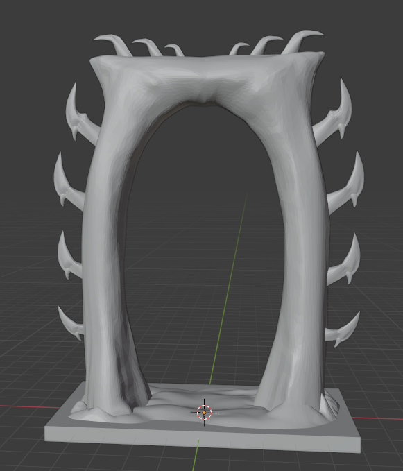
I started off with the spikes, as I knew that once I had a base of them, I could transform and warp it to fit other areas. This seemed to be going quite well, as it was mostly just creating cylinders and cones in blender, merging them and sculpting them to several points.
When it came for the rest of the gate, I started with a single, large cube. First thing was to create a hole in it, of which I learned there are probably a hundred ways of doing it and whatever way I did it probably was the wrong way because it took me half an hour to figure out.
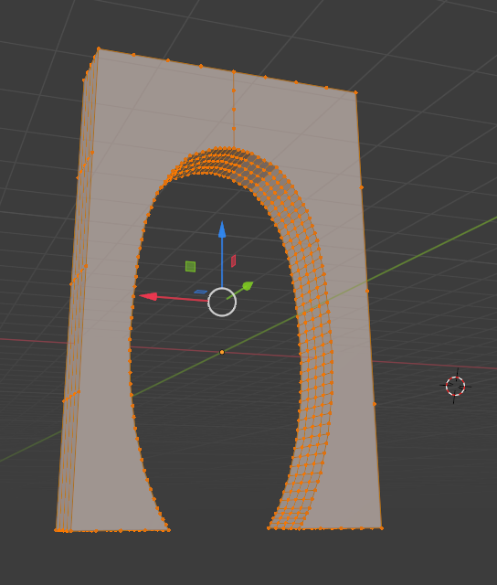
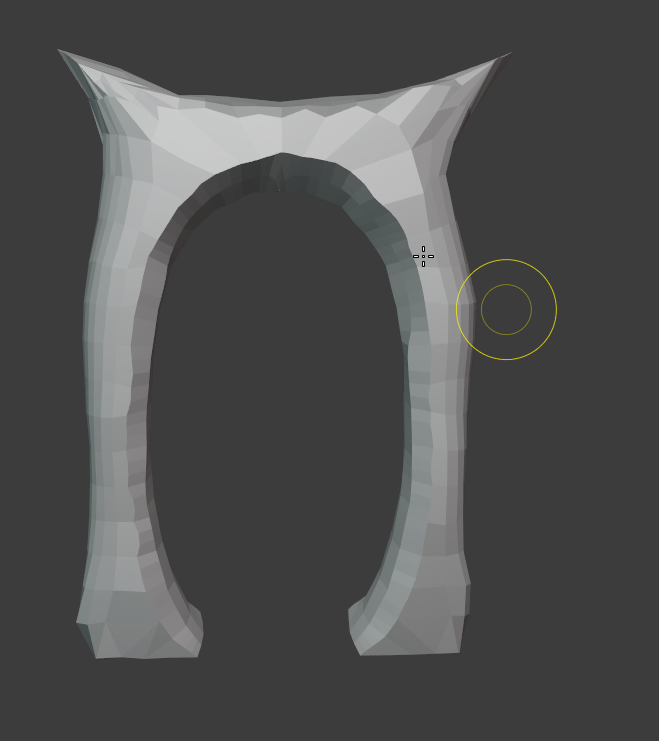
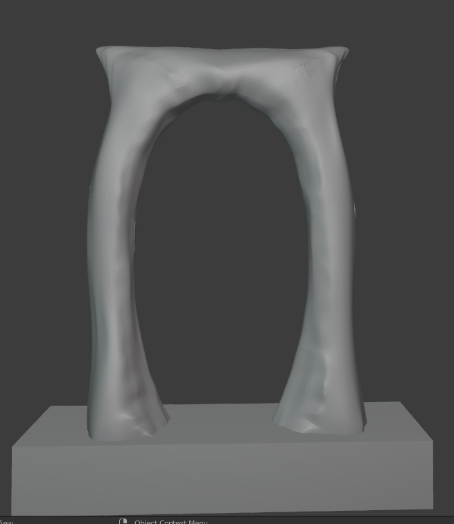
Once that was finished, it was just hours of using the sculpt tool to shape it how I wanted. Giving some texture to the bottom especially, making the perfect arches, and making that iconic 'T' like points on the top. After a couple days of working on it, making a quick rectangle bottom for it, and merging the spikes in, I somehow managed to finish my first ever sculpt in blender!
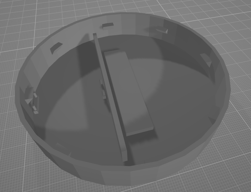
The next steps were to create the base for it, which I'll admit, I could've made prettier, but as I was experimenting I didn't mind the ton of void space I was having. I started out with a simple circle, created a shell with it and make it open-top.
Since I knew I was using an RPI Pico, I got my hands on a 3D model of one and used it to make a mounting area in the 3D model.
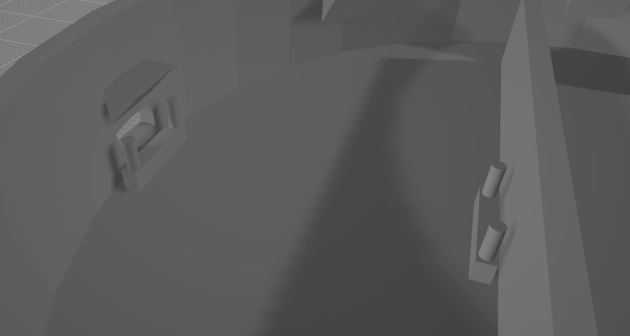
I added a wall in the middle of the base primarily to block light from the LEDs from reaching around and exiting the USB hole for the Pico, but it also served as a backing plate for the microcontroller itself.
Behind the wall I added a raised rectangle platform for the aforementioned LED strip, such that when the acrylic glass is inserted, it doesn't need to go all the way down. Lastly, I added some hanging bits around the sides for the eventual top. Rather than a snap-fit, I opted for a snug fit supported by those hanging things, such that if needed, disassembly for the prototype would be much easier. Spoiler alert - it ended up being a very snug fit, and all those did was stop it from going too far down.
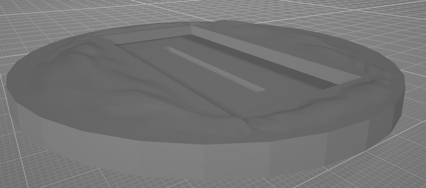
For the cover of the base, it started out quite similar, just as a circle that then had a cutout placement for the acrylic sheet to go through. Additionally, I cut out another section so the flat base of the gate could slot snugly right on it. To make it less boring, I added some mounds to look like dirt and rubble around the top. Just enough texture to be interesting, and not too much to be distracting.
Now that it was all modelled, it was time to print!
Why didn't Dagon just print his portals?
Well he asked for a Maker to do it but got a Mankar instead.
Apologies in advance for the lack of poorly angled printing timelapses, as my Octoprint instance decided to pretend cameras haven't been invented yet during this project.
Printing went quite smoothly. At first I planned to use some PLA but decided that it was experimentation time! What did I end up using? I wish the answer was PLA Plus, but instead it was my first time using PETG. The reasoning was that it is supposedly tougher and can withstand more heat, so if I ever made one of these as a gift to someone, it may be more durable in any condition. Settings were dialed in just right after a few minor test prints, and aside from some annoying stringing and nozzle gunk, it printed quite well - except for some of the tips of the spikes, those were too thin for the layer height I was using and were thus weak.
For printer settings, I did the portal itself in 1.60mm layer height, and the base + base cover in 2.00mm layer height, with some standard PETG settings for everything else. Infill was around 15-20%, gyroid pattern. Come to think of it, this project made me appreciate the gyroid infill pattern a lot more than what I previously used often (hexagons or triangles). The only thing now I like as much as it is Cross-3D infill pattern.
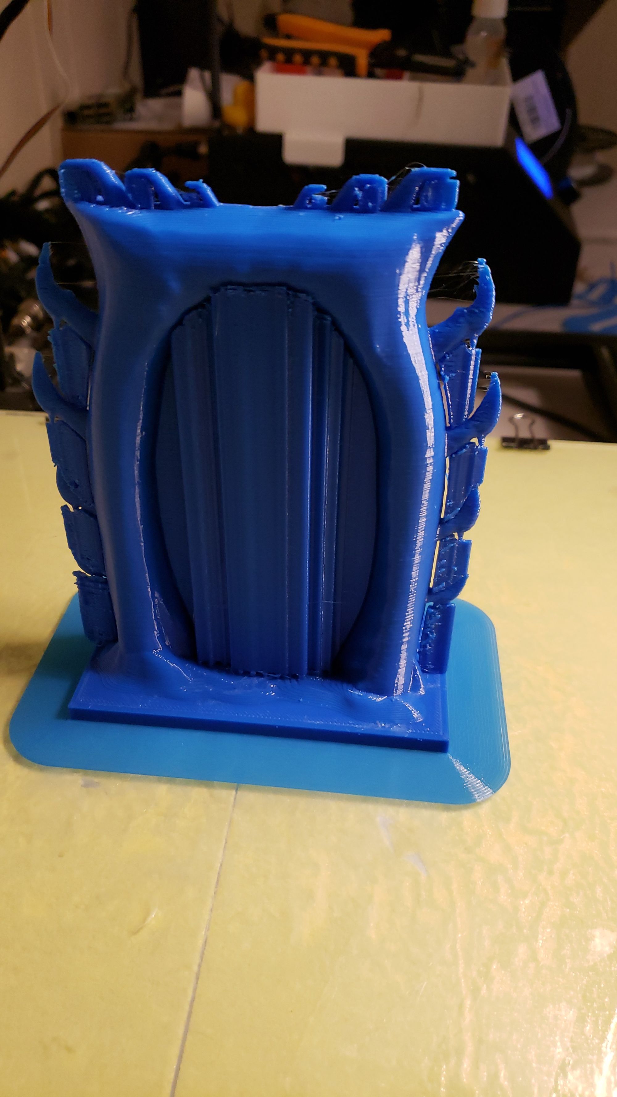
Oh boy did the thick layer height make it look ugly
My reasoning for going with the thicker layer height was mostly because of the time it would take to print it all (spoiler: a while) and also I knew that since it was just for me at the time, I would do a lot more to post-process it with some bondo spot puddy. As far as quality goes, I knew it would look a bit ugly, and some of the spikes were also broken as I was handling it, but this was caused by some issues with my layer adhesion, layer height, and the thinness of those spikes. I say it just makes it look more random.
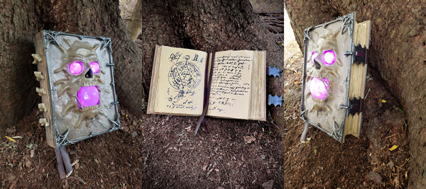
Since I wanted my post processing to blend in the gate and the cover for the casing, I slotted in the portal into its resting place. It was quite a snug fit, didn't even need any super glue!
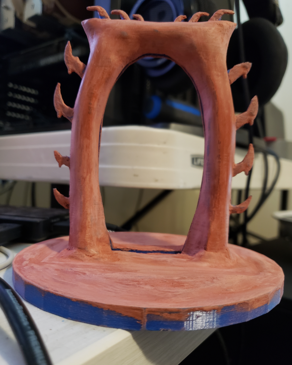
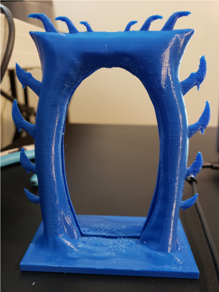
As I was applying more bondo to it, it started to really work its magic making the low poly parts of the model I made look much better (modelled on my laptop, couldn't handle the poly-count so I had to decimate it!). After a few coats of this and sanding in between, it was ready for priming.
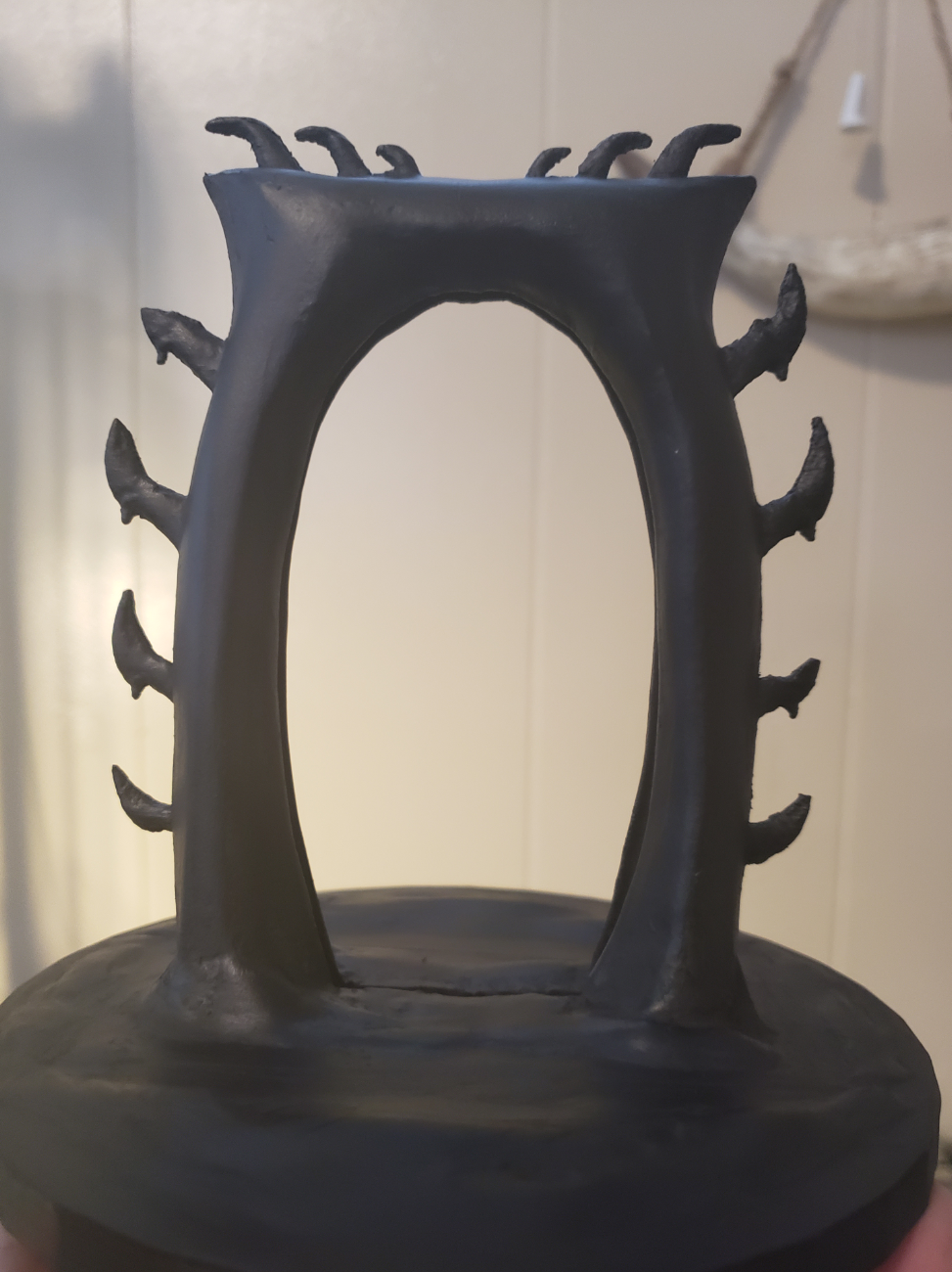
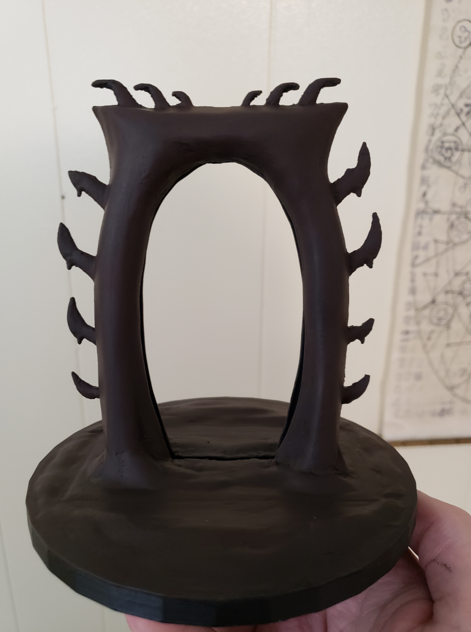
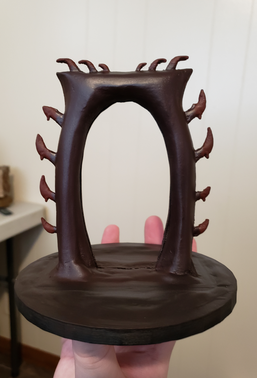
Since I knew I would be smoothing it with the bondo, I didn't bother modelling in rocky textures, so this was going to be a smooth, reddish stoney gate. I started with a matte black primer coat, then mixed several combinations of grey, (various) red, black, brown paints and a few washes of dark to eventually come out with something that doesn't look too bad. In hindsight, I should have some some paint splotches to vary it more, but it still holds up as is.
The base of the casing was painted in generally the same manner, but since it didn't have any texturing detail, it's nothing fancy to look at.
The bane of all Daedra
Lack of proper tools
Next came my least favourite part - the acrylic.
There aren't any photos to go along with this section, and it isn't too interesting except from my bits of frustration. To set the scene, I needed to cut the acrylic into specific sizes. Specifically, the height had to be 12.50cm, the thickness had to be 4mm, and the width could be between 6.00cm and 6.25cm. The wiggle room was in case I had messy cuts and it would be hidden by the sides of the gate.
I ended up cutting it pretty close on the width, as the acrylic sheets I ordered were 200mm x 300 mm x 4mm. This meant with one sheet, I would be able to cut out exactly six "portals". However, this is where the first thing went wrong.
I don't have any proper tooling to cut acrylic. Anytime I've tried the scoring and snapping technique, it always finds a micro-fracture, goes into the middle and best case scenario I get unusable acrylic. Worst case scenario, I get acrylic cutting my hand open and also unusable acrylic. As for cutting, I didn't have any tool for that either. In the past I tried with a small jewelers saw, and that was very uneven and took forever, going through several blades. The only thing I didn't try which I had access to was a chop saw...
Remember how I said I could get six cutouts from one sheet? It included some wastage on the top and bottom, and I knew I had to accommodate for the thickness of the saw blade cutting out a lot of material.
I underestimated how much it would cut out.
I ended up with four usable blanks out of six, with semi messy edges. A lot of debris everywhere in my yard, and a smell of burning acrylic that wouldn't go away for hours. Let's not forget that the sound of the saw cutting into the acrylic could only be rivaled by the screams of newborn children in the depths of hell raised by banshees. At least I only needed one...
This is the only related image I can find of this ordeal, and it was from when I was contemplating which acrylic sheet to order and how I could maximize my blank creation and my cost per blank. Have fun trying to parse my handwriting.
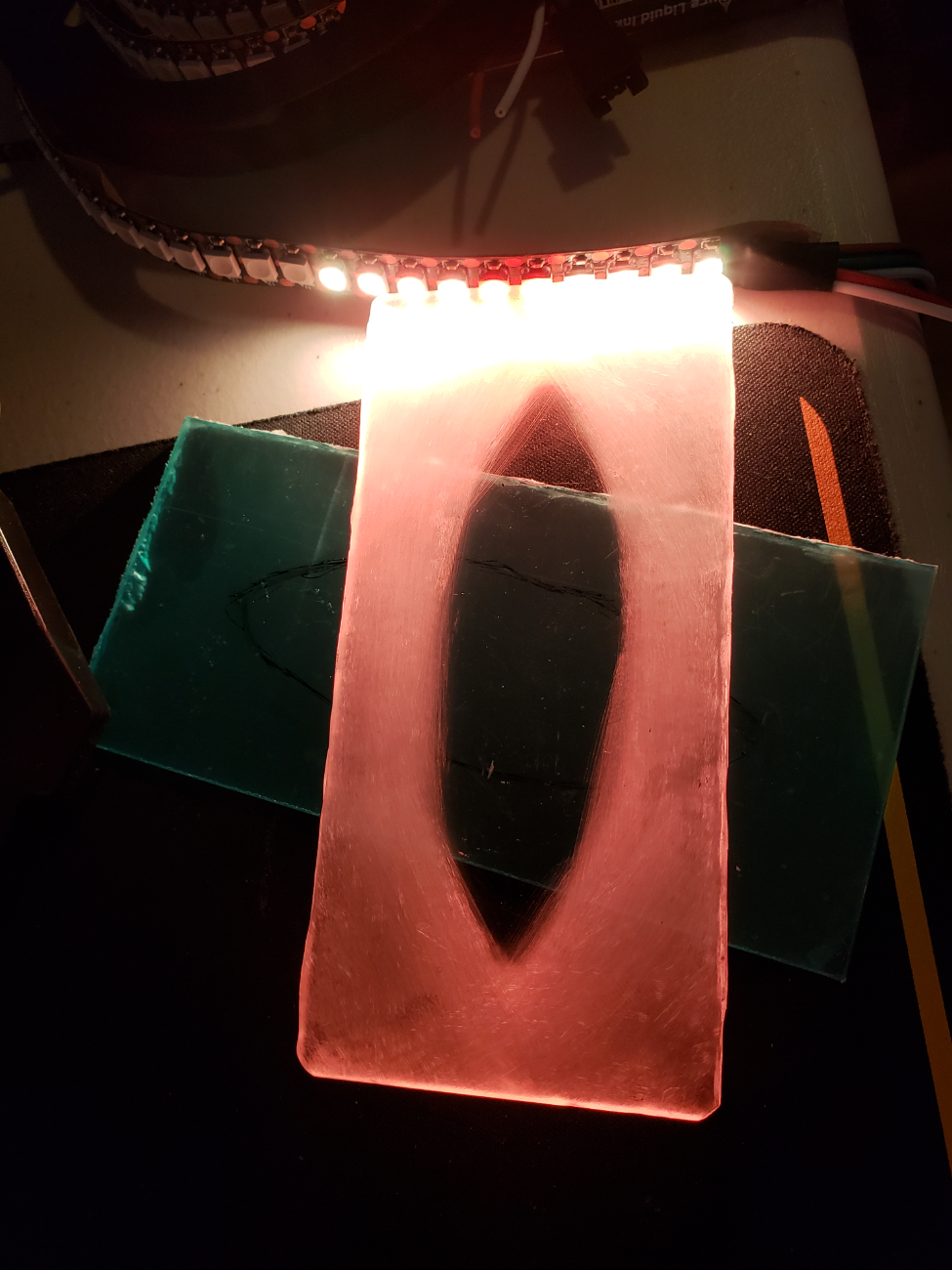
Finally, I took some sandpaper and lightly sanded around the edges of the blank that seemed to be the best of the batch. It's a bit scratched up in the clear part, and unevenly sanded, but from a bit of distance it looks fine and diffuses the light just fine.
OblivionPortal.open()
Error: Akatosh.exe blocked this function from running. Please contact your local Septim.
Now that all the painting is done, it's time for the programming and electronics!
Researching into the RPI Pico, there really wasn't much documentation out there at all about driving some LEDs with it since it was so new, especially self-powering off of its 5v input, since it's USB powered. It took mixing and matching several different early examples to get something working. Luckily, for the 12 LEDs I'm running, it's able to be powered from the Pico easily.
The code is quite simple, and so was deployment. I used Thonny for the first time, to flash the Pico with MicroPython (also the first time using that, though it isn't much different from regular python). After flashing and connecting it to the PC, I was able to run test code on the board.
The script I made to run on the Pico would light up first the LEDs on the sides in yellow, then one by one a few more going towards the centre in orange, only to then light up the centre in red. Once this startup sequence was complete, it would then shift each LEDs RGB values randomly little by little around it's starting colour to give the effect of a portal-like fiery animation.
While the file is attached below, you can also view the gist here.
As for the circuit design, it was quite simple.
Left: Pico Pinout. Right: Circuit Design going to the LED strip segment. Pinout of the LEDs may vary. GPO 0 is used in the code, but can be changed.
After that, simply plug it into the computer using a micro USB cable, flash the Pico with MicroPython and load up the main.py script. To flash the Pico, there are hundreds of tutorials using Thonny.
Testing the code and the diffusion of the acrylic, it lights up quite nicely.
The Oblivion Crisis
"Somebody call an ambulance, but not for me" - The Hero of Kvatch, probably
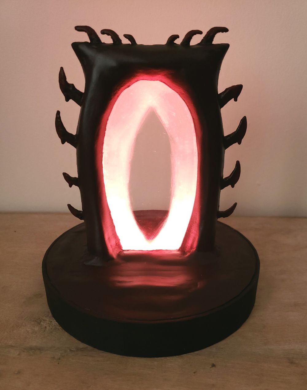
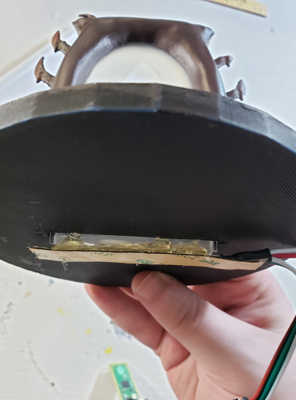
Once the programming was done, all that was left was the assembly, which didn't take too much time as it ended up being a lot of snug fits. The only real assembly was some hot glue for the RPI Pico, and the LED strip, then inserting the acrylic into its slot.
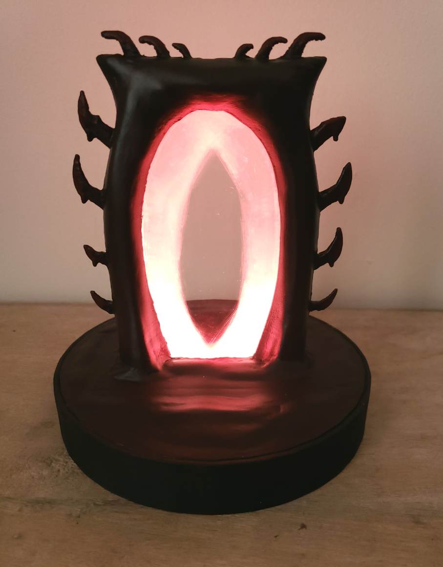
Unfortunately, my phone's camera doesn't do it justice. It washes out the colours, the animation is hard to see, and it well, just doesn't look good on camera. But here's some pictures and videos regardless.
It's interesting for me to see what changed from my initial design to the final product. For example, instead of an LED strip segment, I had planned to use a thin fibre optic cable that has some side-glow functionality and just use one or two LEDs. Unfortunately it was not bright enough, even when wrapped around the whole acrylic. Hence I went with the LED strip which was for the best, as it let me do more complex animation stuff, whereas the fibre optic cable would have only been just colour blending if anything.
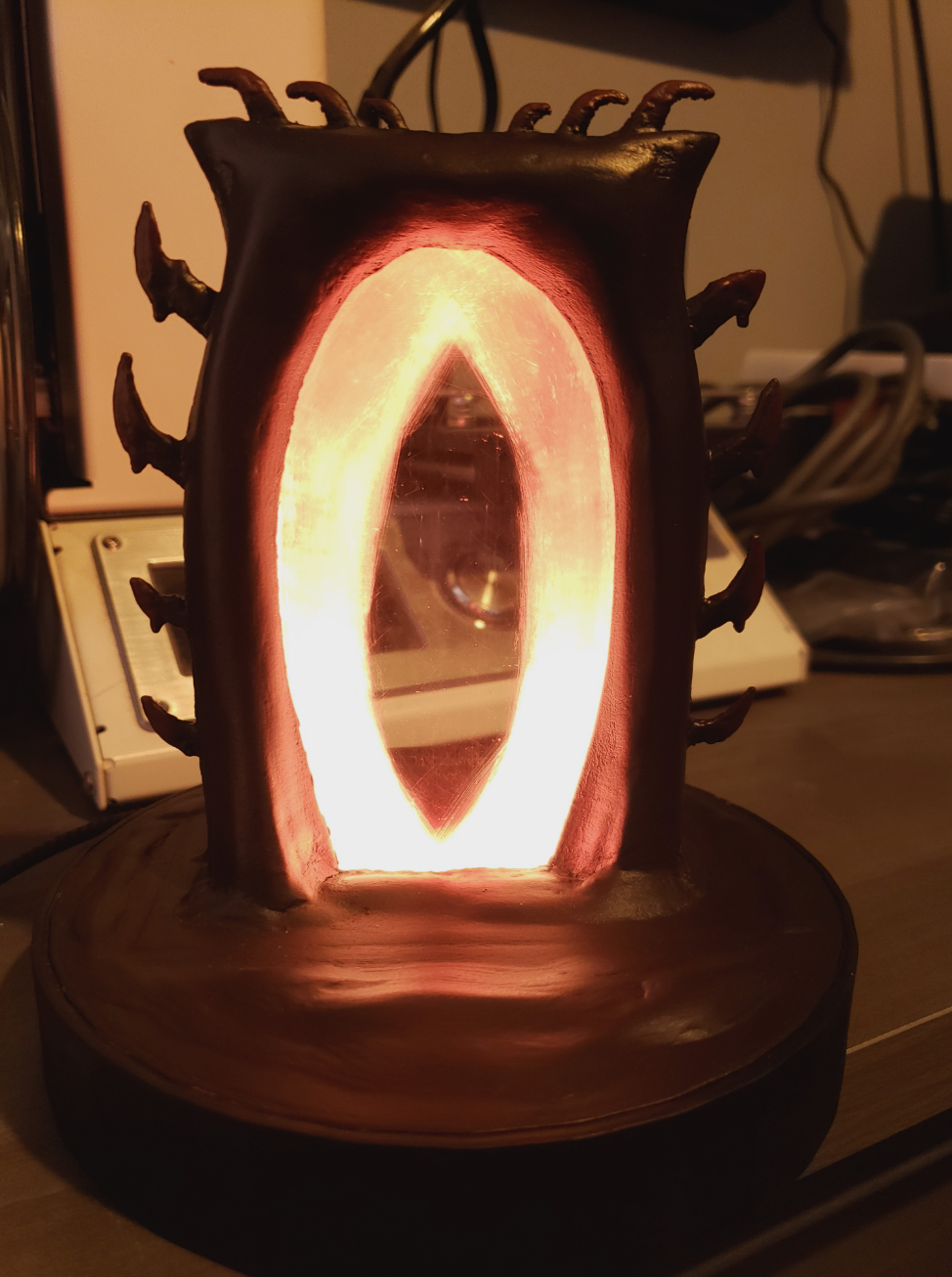
In the dark, the camera can slightly pick up the animation. It's a lot more animated in real life
Fun fact: Around the time I finished this, there was an eclipse and the sky actually went red as I had this plugged in.
Resources
Everything I used and file resources for you
Materials
- PETG 3D Filament
- Bondo Spot Putty
- Sand Paper
- Raspberry Pi Pico
- Micro-USB Cable
- Some electronics wire
- Acrylic Sheets (4mm thick, minimum 60m wide, 125mm high)
- Black Paint Primer
- Various Acrylic Paints (Go for a red-stone look)
Tools & Equipment
- Any 3D Printer (I used a heavily modified CR-10 v1)
- Soldering Iron & Solder
- A computer
- Optional: Raspberry Pi running Octoprint for the 3D Printer