Bambulab Smart Accessory Control Box
Here you can see how to setup a smart accessory control box on your Bambu Labs printer to control the power to either additional lighting or a Bentobox!
This project will use ESPHome, MQTT and Home Assistant. This guide will also require some soldering.
Requirements
Materials
Some of the links below are affiliate links
- Wemos D1 Mini
AliExpress, Amazon - 4-Channel Mosfet Board
AliExpress, Amazon - DC to DC Buck Converter (12-24v to 5v)
AliExpress, Amazon (Check images below for right one) - 4x Male Barrel Jack Plugs
AliExpress, Amazon - x4 M3 8-10mm Screws/Bolts
Amazon - 5 to 12 6x3mm Magnets
AliExpress, Amazon - 22 AWG wiring
Amazon - Power Supply* (Details depend, see below)
Amazon
Software
- ESPHome
- MQTT Broker (Optional)
- Home Assistant (Optional)
Tasmota can work instead of ESPHome if you know how to make your own config for it.
ESPHome & Code
This code makes a few assumptions of you having ESPHome setup, such as a few secrets attributes setup.
Secrets Attributes
- mqtt_broker: IP of your MQTT broker
- mqtt_user: Your MQTT Broker User
- mqtt_password: Your MQTT Broker Password
- ota_password: Your OTA password
- wifi_ssid: Your primary wifi ssid
- wifi_password: Your primary wifi password
- bkp_wifi_ssid: Backup Wifi SSID
- bkp_wifi_password: Backup Wifi Password
- ap_password: Backup Hotspot password
These can be modified or even removed if you know you don't need them. Additionally if you choose to use the HA api integration instead of MQTT, you can remove all the mqtt info and uncomment the API and set ha_encryption_key.
The reason for not setting up a standard template is due to the number of other configuration items that need to be modified.
The code can be found here or embedded below.
This code also makes the assumptions for the power plugs and PWM switches. The first plug is for accessory lighting called "Bambu Top Lighting". The second plug will be for controlling the BentoBox fans called "BentoBox Fans".
Plugs 3 and 4 are setup for PWM but do not have an entity for the API to use and as such as rendered disabled for now. If you want to use them for something, modify the code following the pattern to add an additional controllable entity using _3_pwm_output and _4_pwm_output.
Both the light and fan switches will also track estimated power usage. I recommend using a Kil-a-watt or other measuring device to find the max power draw in watts for your lighting and then again for your bento box fans. For me, my COB LED strip uses ~17 watts at max brightness, and my 2x 5015 blower fans use 4.6 watts at max speed. The math for scaling down to power usage is not precise (linear, which is not real-world) but will be good enough for most people. Modify these values with your measurements.
After you've modified or reconfigured your ESPHome YAML code, connect your D1 Mini to your computer and prepare to flash it.
Wiring & Assembly
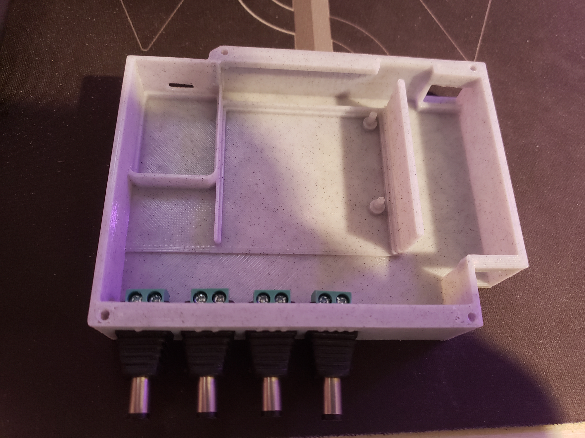
Link to the case model on Printables.
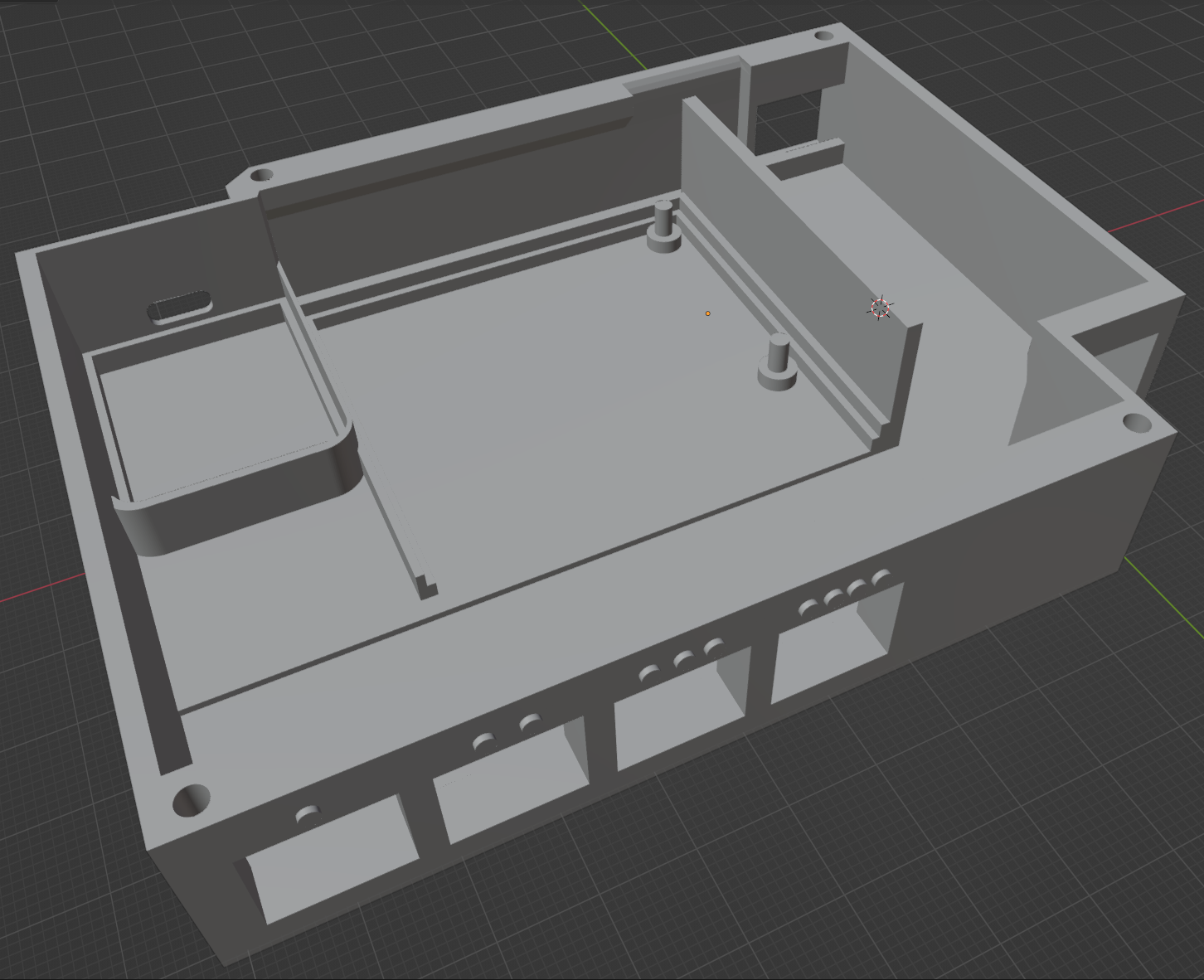
The print requires no supports at all and is only two pieces. I recommend PETG for both good heat resistance and zero to low shrinkage. PLA will also do just fine.
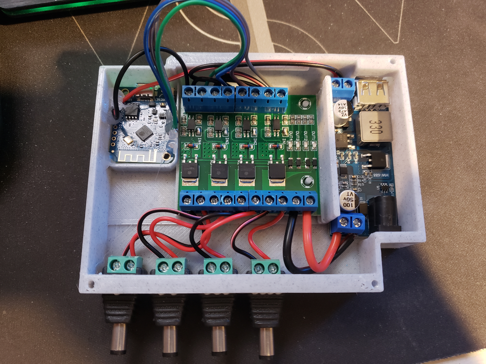
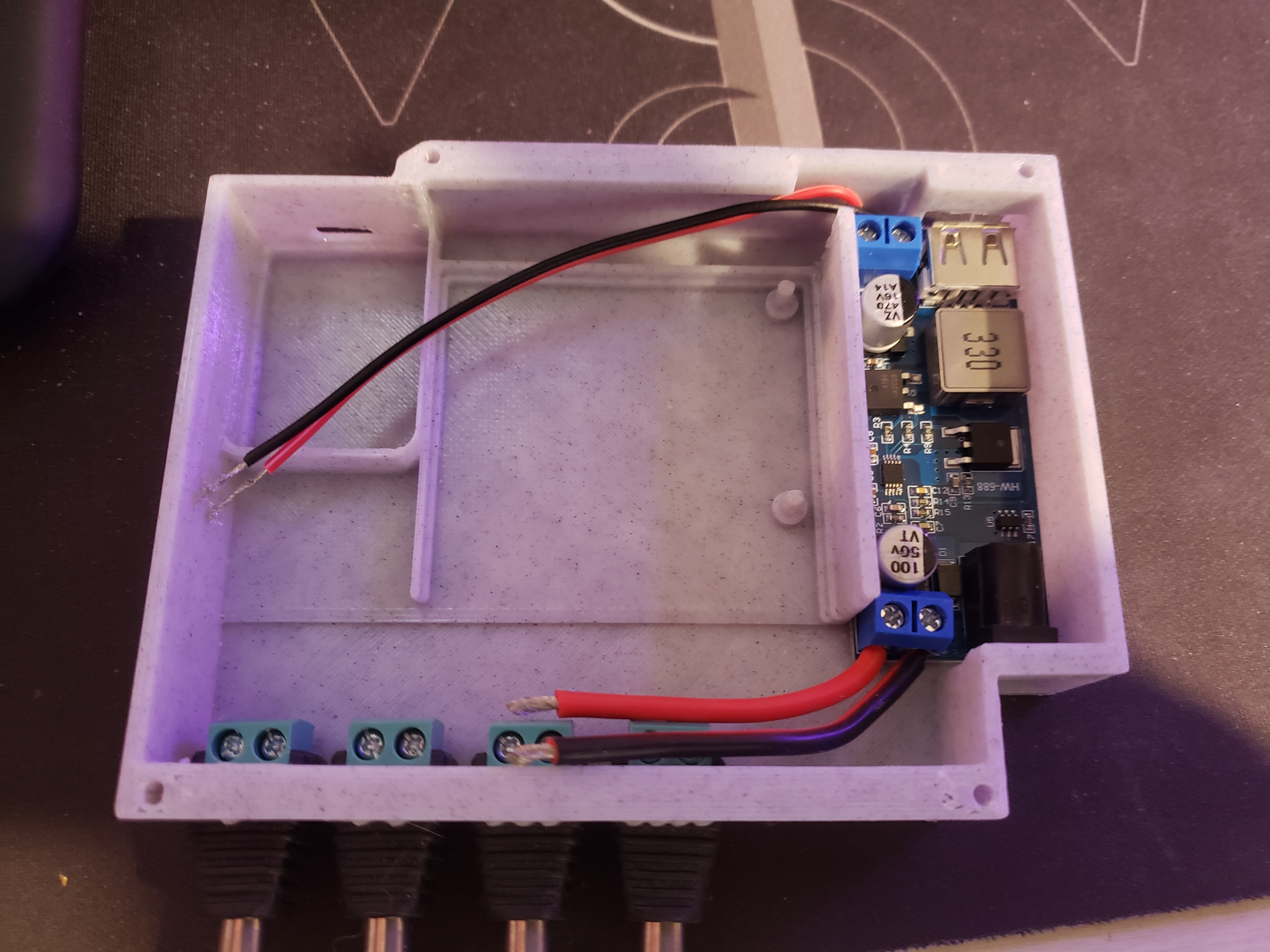
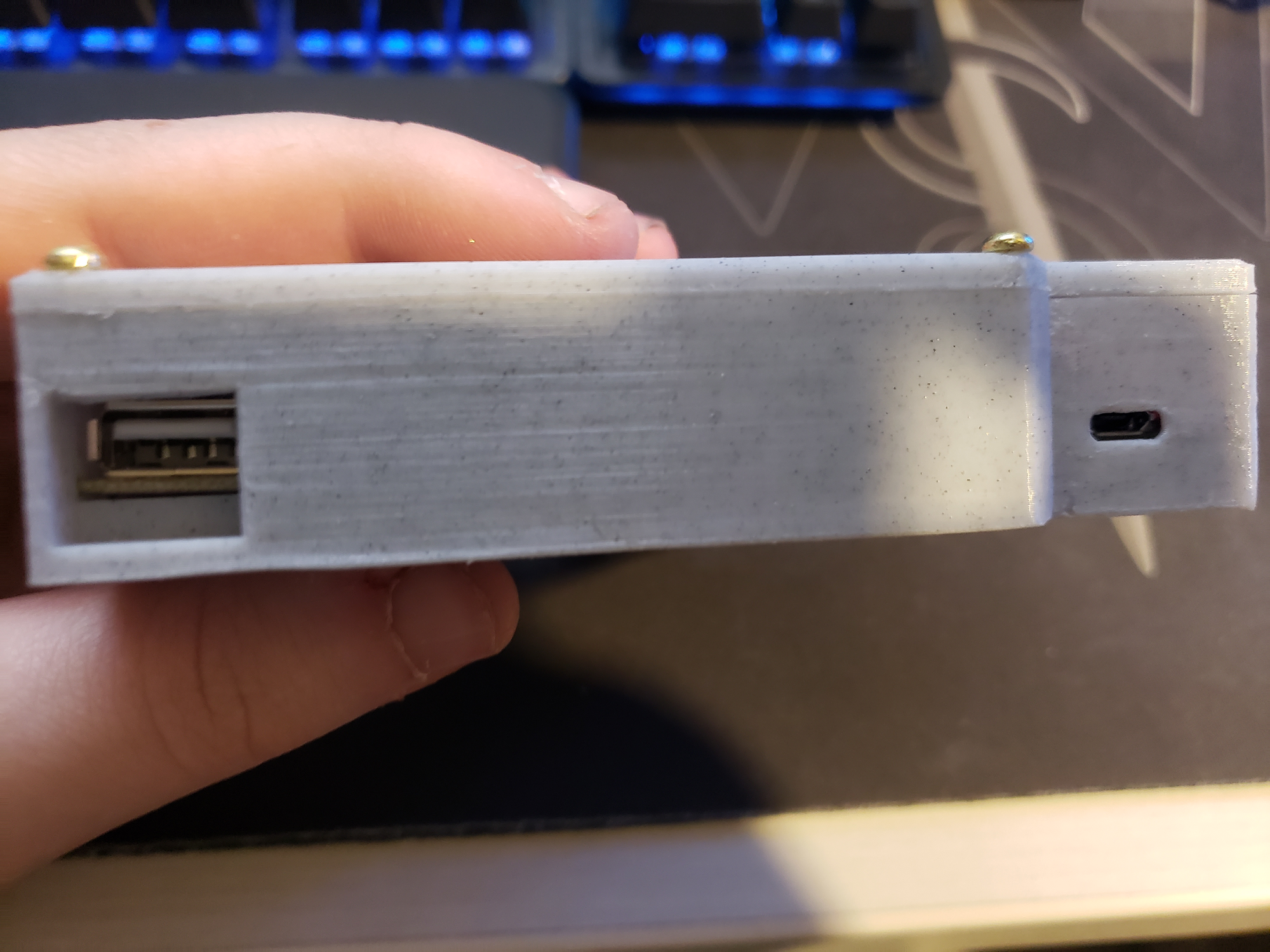
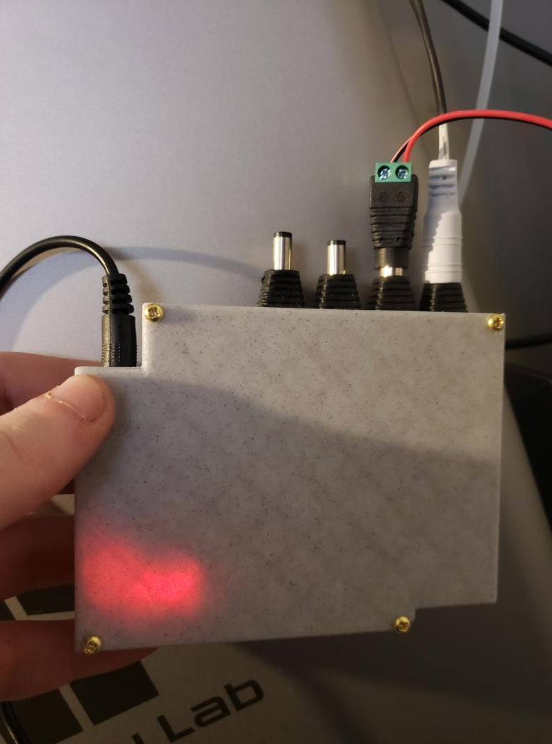
The power input will be going into the DC Barrel jack on the buck converter. This will either be 12v or 24v, and I recommend at least a 2A power supply. Whichever you choose for a power supply will be the matching power your accessories will get. The buck converter is friction-fit in place. It also has an exposed USB port for powering any 5v USB devices if you so choose.
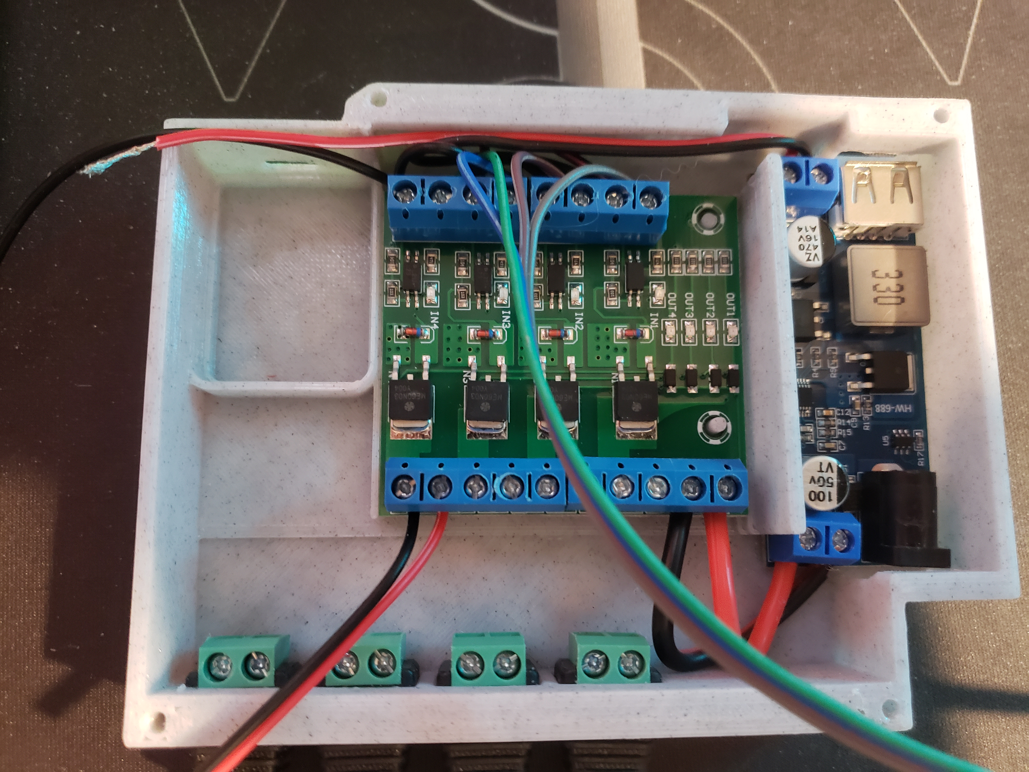
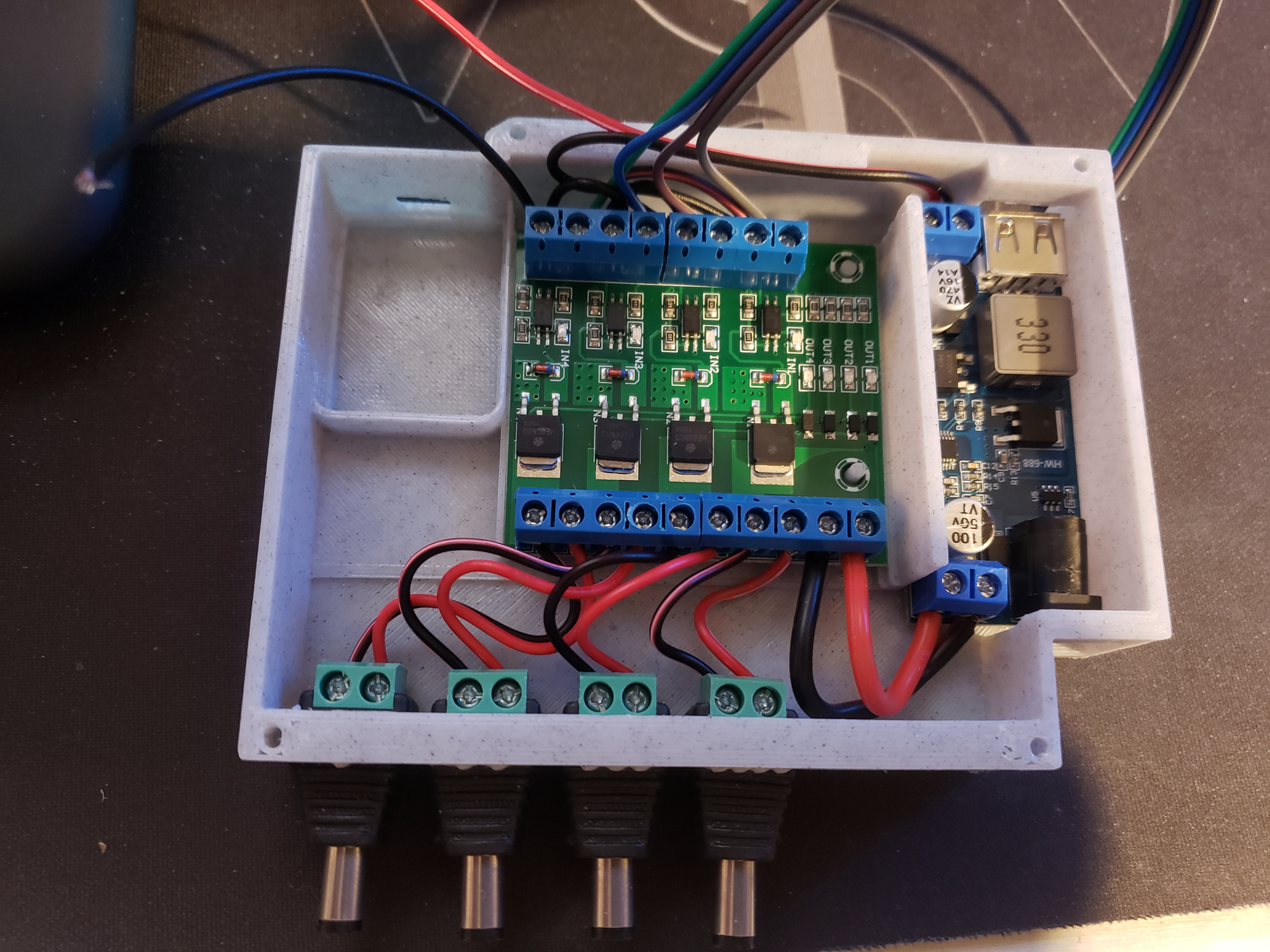
The screw terminal for power input on the buck converter will be used as additional power output of the original voltage. This will go into the power input of the MOSFET board. The MOSFET board is friction-fit in place.
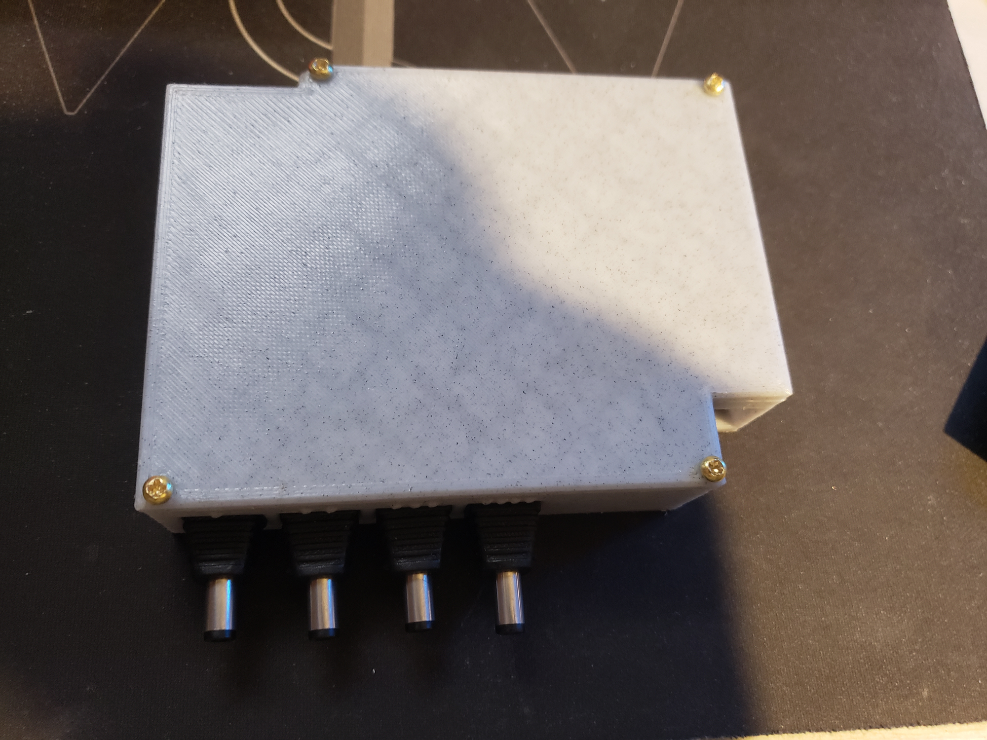
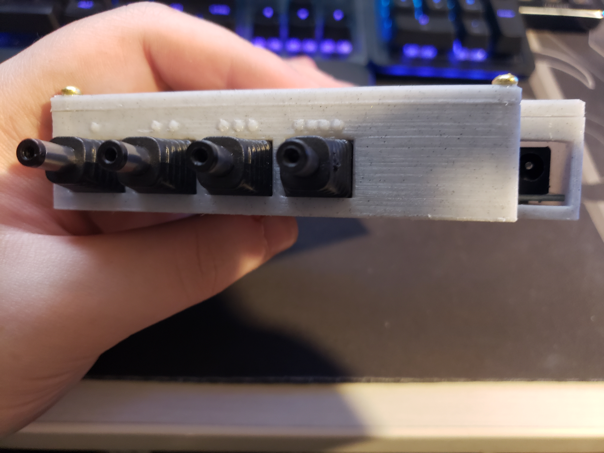
Each terminal pair will be wired to a corresponding male DC barrel jack that are friction fitted into the front of the control box housing. The reason for using male plugs is for standards - power source is usually male, power in is female (i.e., your lighting or bento box).
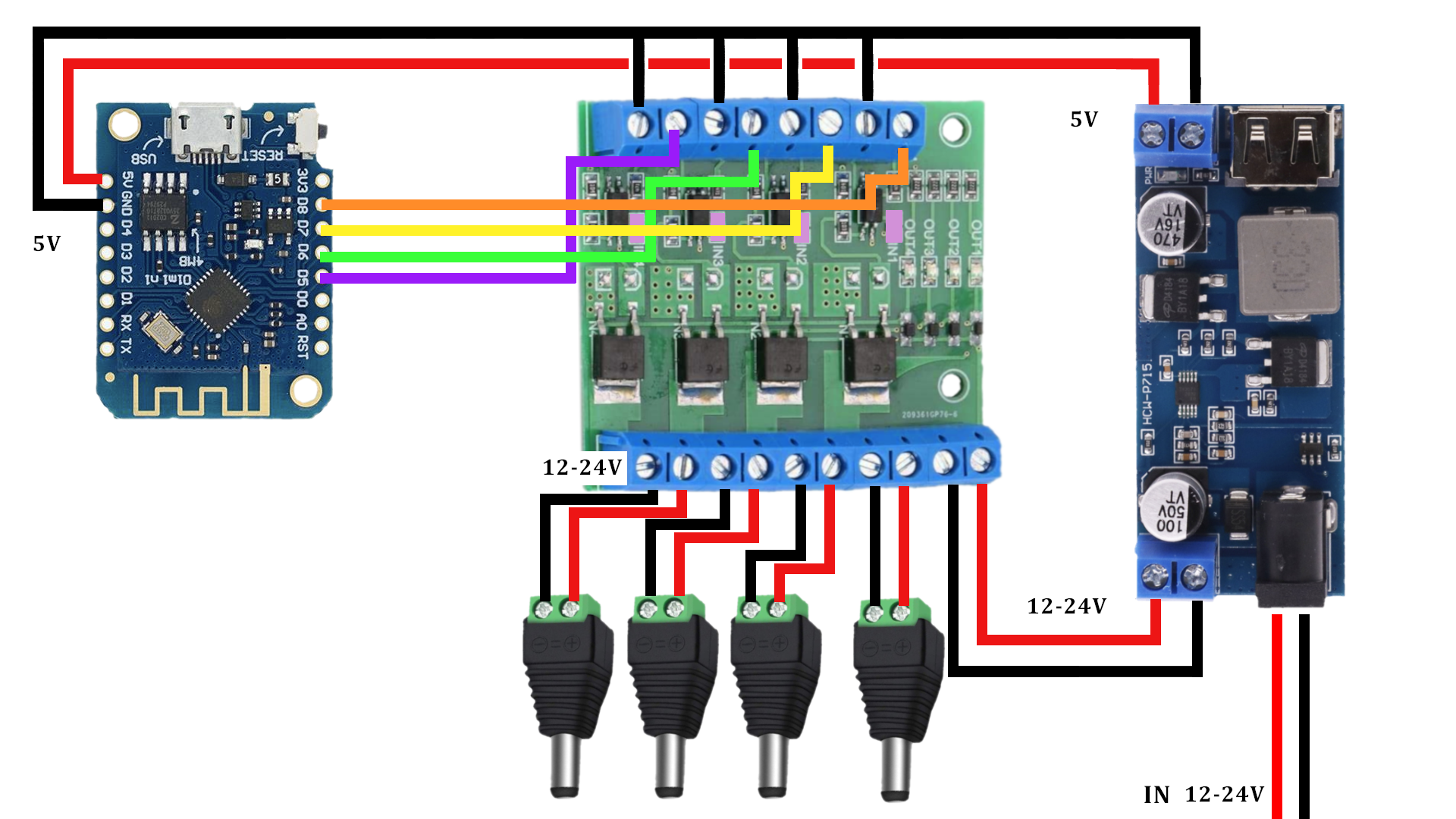
The 5v power output of the buck converter is used for the D1 mini. The 5v+ will go directly to the 5v input pin on the D1 mini. The ground will be (lazily) bridged by connecting it to the ground terminal for the 4th PWM input on the MOSFET board, then with smaller wires birdge the 4th to the 3rd, 3rd to the 2nd, 2nd to the 1st, then connect the 1st to the GND pin on the D1 mini. Feel free to reorder ot bridge the grounds in another method if you so choose.
For the PWM signal pins, D5 connects to the first + input on the MOSFET board, D6 to the 2nd, D7 to the 3rd and D8 to the 4th. With how the current ESPHome code is setup, the first and second will be for accessory lighting and bento box fans, respectively.
The D1 mini is not friction fitted into place as not all D1 clones are the "exact" same size, and some without screw holes as well. As such, I recommend hot-gluing it into place. I also recommend hot-gluing the wires soldered onto it for strain relief. There is a hole so you can still access the micro-usb port. I recommend testing before hot-gluing everything in place.

The red status LEDs are fine to keep in place.
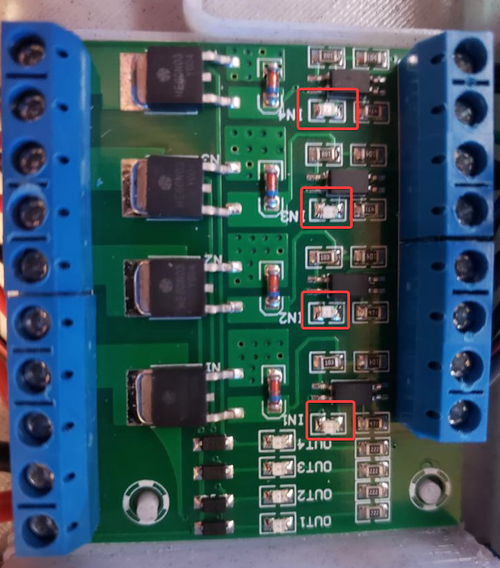
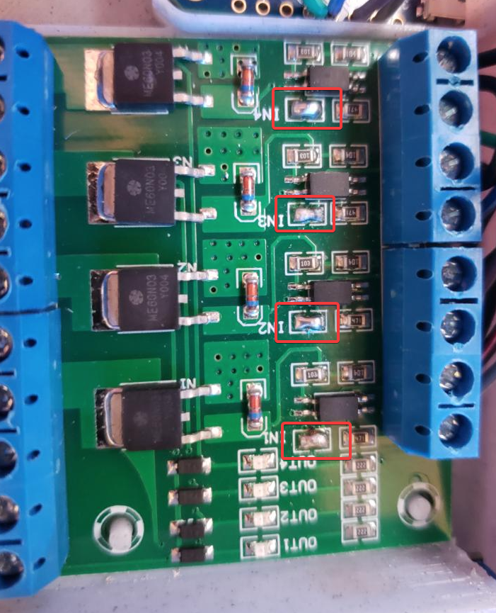
Left: Original board with the LED issue. Right: The fixed board, LEDs are removed and solder pads are bridged
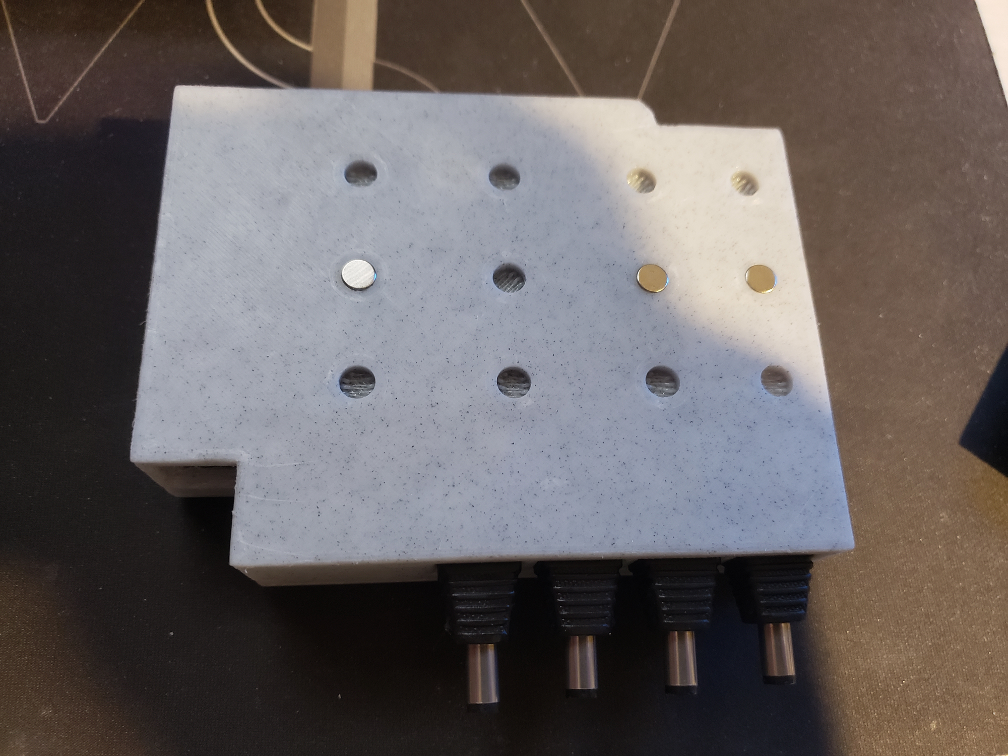
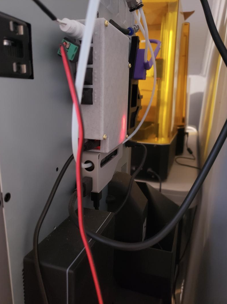
For the case, attach the top by screwing in the 4x M3 screws in the holes provided. To attach the box to the back of your printer, there are 12 holes on the bottom for holding 6x3mm magnets. They are spaced out depending on what you feel is the best layout. I recommend 4-5 magnets for stability based on the weight of the box, however feel free to experiment with as many or as few as you want. The holes may require a bit of glue for the magnets if they do not friction-fit in.
Finishing Touches
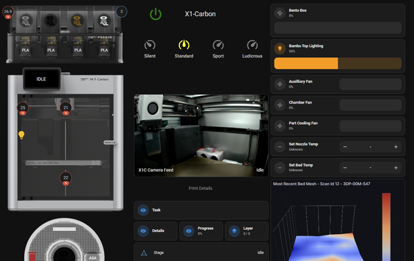
For my setup, I am using the following riser with 24v COB LEDs, and this remix of the bento-box using 5015 blower fans. In HomeAssistant, which my MQTT broker is connected to, the Bambu-Accessories device is automatically picked up.
With it, you can now control the brightness of your LEDs and the speed of your bento fans.
With this and my previous guides integrating the Bambu X1C into HA, you can create several automations such as:
- Turn on/off the lights on printer startup/shutdown (via smart plug trigger or when state changes to or from OFFLINE)
- Turn on/off the lights when LIDAR is in use or not
- Turn on the bento box fans when ABS, ASA or an Unknown filament is being printed with, and turn off 10 minutes of print being "FINISH" or "FAILED"
- Dim the lights based on time of day
- Pre-set the values to lower than 100% to increase the longevity of lights/fans, reduce noise or heat etc.
- If you use an addressable RGB strip instead, modify the ESPHome yaml to make it controllable too!
And the list goes on and on!
Wrap Up
If you have any questions, concerns or ideas, feel free to message me on Discord (@wolfwithsword), Twitter (@_WolfwithSword) or contact me through here.
Feel free to also post your Makes on the Printables page!